
General Electrical Inspection
EN 60204-1
1. Scope
This specification is supplementary to IEC 60204-1 and establishes the minimum requirements for all electrical instrumentation and process control systems of machines and related installations
2.Normative references
This specification is complementary to standards and regulations of
IEC - International Electro Technical Commission
Europe
EN - Europäische Norm , European Standard
CENELEC - Comité Européen de Normalisation Electrotechnique
DIN - Deutsche Industrie Norm (German Industry Standard) VDE - Verband Deutscher Elektrotechniker
3. Incoming supply, conductor terminations and devices for disconnecting and switching off
The incoming supply shall be terminated according to IEC 60204-1 and adapted to the required local conditions.
Main switches shall be lockable only in the OFF position. It must be possible to secure them with padlocks.
4. Protection against electric shock
In general the shock protection measures shall comply with IEC 60204-1 using enclosures with the specified IP ratings and appropriate barriers.
 In addition, socket outlets (e.g. 230 VAC) either mounted in the cabinets or on the machine structures shall be protected with an ground fault circuit interrupter GFCI (In = 30mA). In addition, socket outlets (e.g. 230 VAC) either mounted in the cabinets or on the machine structures shall be protected with an ground fault circuit interrupter GFCI (In = 30mA).
5. Protection of equipment
5.1 Electrical protection
Motor circuits shall be protected by Motor Circuit Breakers (MCBs) which provide both short circuit and overload protection. Only one MCB per motor is allowed.
5.2 Environmental protection
In general, all equipment and enclosures shall be suitably IP rated for the planned environmental conditions and shall be a minimum as follows:
‧Control cabinets, terminal boxes, etc
‧Motors
‧Limit switches, Proximity switches etc
‧Valves
After opening of the cabinet door, still protection IP20 must be kept.
6 Equipotential bonding
6.1 General
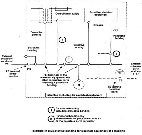
This chapter provides requirements for both protective and functional bonding. (Figure 1) illustrates the concept.
Protective bonding is a basic provision for fault protection to enable protection of persons against electric shock from indirect contact.
The objective of functional bonding is to minimize the consequence of an insulation failure which could affect the operation of the machine, and consequences of electrical disturbances to sensitive electrical equipment which could affect the operation of the machine.
Each individual electrical and control system shall fulfill requirements for both protective and functional bonding and shall follow recommendations in IEC 60204-1 and in this document.
( Figure no.1)
6.2 Protective bonding
The protective bonding circuit consists of PE terminals, protective conductors, conductive structural parts of the electrical equipment and conductive parts which form the structure of the machine.
All parts of the protective bonding circuit shall be designed to withstand the highest thermal and mechanical stress that can be caused by earth-fault currents.
If an IT distribution system is used, the machine structure shall be used as part of the protective bonding circuit in conjunction with an earth fault supervision system.
No switching devices can be included in the protective bonding circuit.
Metal cable ducts and metallic cable sheaths shall not be used as protective conductors, but they will be connected to the protective bonding circuit.
Each lids, doors, cover plates , where the electrical equipment is mounted , will be protective conductor used to ensure the continuity of the protective bonding circuit.
Each protective conductor connecting point shall be marked or labeled as such using the symbol 60417-2-IEC-5019. Terminals for connection of protective conductor will be identified by the bicolor combination GREEN-AND-YELLOW.
6.3 Functional bonding
Protection against maloperation caused by insulation failures is achieved by
connecting to a common conductor.
Therefore the respective method for protection against maloperation due to
earth faults, voltage interruptions and loss of circuit continuity must be
followed. Please see specific details in IEC 60204-1.
In case that a sensitive electrical equipment is used (control units, measurement units, etc.), a separate connection to a noiseless earth is required.
Also the following measures must be implied:
to use TNS system for both power supply cables and machine electrical system if there is a combination of TNC system for power supply cables and TNS for the machine electrical system, the point of separation from PEN conductor to PE and N conductors must be additionally connected to the noiseless earth conductor equipotential system must be formed in star connection. See example in Figure no.1
if shielded cables are used, special care must be taken for correct connection of their shield to the protective bonding circuit. Supplier requirements for installation to be followed
7 Control circuits and control functions
7.1 Control voltage
24 Volt DC
Exception: 230/120 Volt AC for heavy loads (e.g. large contactors, hydraulic valves etc.) Requires written confirmation from Continental.
All inductive loads connected to 24 V DC shall be equiped with overvoltage surpression.
7.2 Emergency stop
Use of emergency stop units or safety PLC is mandatory. Mushroom switches and cord-pull must lock and shall be equipped with trip indication and be monitored by the control system.
7.3 Transformer
Coil windings of the control transformers shall be isolated from each other. The secondary winding(control side) of the control transformer must be linked to the protective conductor system.
7.4 Monitoring of steam, pressed air, water, temperature etc.
All critical services (steam, pressed air, water, etc.) required for the operation of the machine are to be monitored.
Every cabinet shall have temperature monitoring (PT100).
In case of over temperature an alarm should be visualized.
8 Control gear: location, mounting and enclosures
8.1 Mechanical arrangement
The cabinet design shall be separated into feasible units if the total length exceeds the transportation limits. Terminals shall be installed for the necessary wire connections between the separated units. Those terminals shall be identified in the circuit diagrams.
Control cabinets shall have ring lugs attached to them for the transportation of the fully equipped units.
The doors (each leaf having a maximum width of 900 mm) must open to an angle of at least 95° and be designed in such a way that control cabinets can be installed alongside each other. Zinc plated mounting plates shall be used (see EN / CE rules).
Each cabinet door is to be equipped with a locking system with push button inlet, prepared for a locking cylinder.
9 Conductors and cables
Control cables must be flexible and at least multi stranded conductor cables.
The wiring of the machine outside the control cabinet and control panel is to be effected using multi- conductor cables ( numbered types ). Wires should have the same number from end to end. In the case of cables with more than seven conductors, at least 10% of the wires are to be kept spare for modifications and repairs ( exception : main power cables ).
Cables which are subjected to frequent movement during operation must be highly flexible and be suitable for the specific requirement.
For servo drives and AC drives with frequency converters generally the guidelines of the supplier shall be fulfilled (shielding etc.).
Installation and connection of field bus cabling shall be according to suppliers specification.
All cables to have a label tag at each end of the cable. The label should be suitable for the environment.
All wires inside the electrical cabinet to be according IEC 60204
10 Wiring practices
All single conductors and cables shall run continuous without splices from
terminal to terminal.
Shielded cable drain wires to be carried through terminal blocks.
No terminals or terminal connections are allowed in wiring channels.
Loose terminal strips must not be used. Terminals with different potentials shall be clustered and shall be separated from each other. All connections must be by means of terminals or plugs.
Soldered connections are not permitted except for data and measurement cables. Spring loaded terminals are preferred. In case of screw terminals all conductors must be terminated with insulated ferules or cable lugs.
No more than 65% of the nominal cross-section of cable channels or ducts is to be occupied. All cables have to be protected by metallic cable ducts (main cable channels).
Cables leaving the main cable channel shall be protected until the last 15-20 cm in flexible conduits or metal pipes. The usage of plastic cable ties shall be limited to the absolute minimum; spiral protection is preferred in any case. Signal and power-cables outside the cabinet are to be placed in separate cable channels or at least separated by a partition if only one channel can be used.
10.1 Wiring / Labeling / Marking
Color code:
The color coding for wires has to be in accordance with the EN60204-1:
BLACK: AC and DC power circuits
RED: AC control circuits
BLUE: DC control circuits
ORANGE: Interlock control circuits supplied from an external power source
CONTACT US
|